Reverse engineering a chinese segway: working principles of motor control
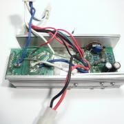
After dismantling chinese copy of segway I wanted to check how the controller is made. After a couple of hours of work with multimeter, pen, a sheet of paper and Kicad I came up with a block diagram and schematic of motor controller. This motor controller is made in a cheap and a very simple way. Reverse engineering and analysing this unit is a very good way to learn the basics of motor control. Here are some pictures of dismantled motor controller:
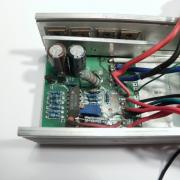
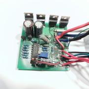
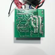
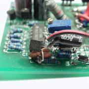
Motor controller consists of three parts - motor controller board, motor direction control board and main power relay. You can see those parts in the first picture (main power relay was removed, thus there is empty space between boards). Main power relay and motor direction control board were fixed to the botton of the box by double sided duct tape. Motor controller board was fixed properly. PCB was pushed in the grooves of the walls of a box. Power transistors were fixed by a metal plate which was screwed to the wall. Because this controller had burned, I changed power mosfets and had to modify this part a little bit. Originally there were two mosfets and one freewheeling diode in TO-220 case. I did not have appropriate diodes by hand, so I replaced it with two mosfets. Original metal mounting plate was too short to hold four TO-220 devices. I had to make a longer aluminium plate and drill one extra hole to fix it properly to the wall (picture 2). As it is visible from the third picture, there were some modifications (at the bottom part of the board) done after the board was manufactured. One modification, voltage delay circuit (transistor, electrolytic capacitor and resistor in picture 4) was made by assemblers of this device, and the other (blue multi-turn potentiometer) was made by me - it allows to change over-current protection limit. The topic of this post is motor controller, so only this part will be discussed further.
Short description and working principles
Image 1. Block diagram of DC motor controller
This controller allows to change motor's power gradually according to a throttle position. In theory there are many ways to change the applied electrical power to the motor, but in practice mostly PWM (Pulse With Modulation) tecnique is used.
Basic theory of PWM is very simple. If you want to apply zero/no power to a device (wether it is a DC motor or for example, a light bulb), you switch off the device (i.e. disconnect it from the power source). When you want to apply full power, you just switch the device on (i.e. connect it to a powe source). What would you do if you wanted to apply 20% of the power to the device in a specific period of time? Very simple - by switching the device on and off continiously, switching it on for 20% of the time and off for the 80% of the time. For example, if you switch the device on for 20 seconds, then switch it off for 80 seconds, then switch it on again for 20 seconds.. In long term, this will be equal to applying 20% of the maximum power to the device. There are two parameters, that describe PWM: period/frequency and duty cycle. Period/frequency in given example would be 100 seconds(i.e. 20s+80s) or 0.01Hz (frequency is measured in Hertz and equals 1/period), and duty cycle 20% (20/(20*80)). Duty cycle is the parameter that changes controls the power applied to the device. Frequency does not make any difference in power.
Controller has additional over-current and under-voltage protection circuits. It was clearly seen that for some reasons after the controller was build, manufacturer added additional circuit. This circuit prevents voltage from throttle sensor to rise quickly. This does not allow to increase power rapidly, which makes it feel that the vehicles powertrain is weak.
Motor controller could be divided into 7 functional blocks (refer to block diagram Image 1): triangle wave generator, throttle, voltage delay circuit, comparator, under-voltage and over-voltage protection, gate driver and power stage.
Triangle wave generator generates a triangle wave signal. In reality it is not accurate triangle wave, but let's assume it is for now. Throttle sensor outputs voltage related to position of a pedal. Comparator compares two voltages (voltage from throttle position sensor and triangle wave generators output) and outputs supply voltage if pedal sensors output voltage is higher than triangle wave generators output, or 0V otherwise. Because voltage on triangle wave generator is changing, output of comparator is changing in time with the same frequency as triangle wave generator's. This forms a PWM signal, where duty cycle depends on throttle position sensor's output voltage. Gate driver amplifies current of this PWM signal and passes it to power transistors. Power transistors are switching motor on and off, according to the signal. This allows controlling power supplied to the motor gradually.
Over-current protection circuit measures current flowing trough power transistors. If it detects that it is higher than preset value, it short circuits the input of a comparator to ground, making voltage on it 0V, thus PWM signal duty cycle 0%.
Under-voltage protection circuit works the same way - it measures battery voltage and if it falls below preset value (it happens when battery is near empty), it short circuits the comparator's input to ground.
More theory
For those, who are interested in more detailed operation of motor controller, the schematic cicuit is shown in Image2. There might be some mistakes in the circuit, but it is drawn only to explain working principles of this motor controller. After the picture there is a brief description of all the main parts.
Image 2. Schematic circuit for DC motor controller
Triangle wave generator
This part of controller is made of one comparator (out of four in LM339 IC). You could find similar schematic for a square wave generator on the internet. The only difference here is that output signal is taken from a timing capacitor, where it has a form, similar to triangle. This is one of two essential parts for PWM signal generation.
In the images above you can see waveforms on comparators output pin2 (left image) and comparators negative input pin4 (right image). Frequency of both signals is approximately 13.3kHz. Notice "triangle" wave is changing between approximately 1V and 4V.
Comparator
As known from electronics theory, this part compares two voltages applied with negative (6pin) and positive (7pin) input terminals. When the voltage on a positive input is higher than on a negative input, output voltage (on pin1) is the same as comparator's power supply, otherwise it is tied to ground (outputs 0V). This is the second essential part for PWM signal generation.
Throttle
Throttle pedal has a magnet and a linear hall sensor inside. Linear hall sensor is powered from 5V circuit. Hall sensor's output voltage changes according to the position of the magnet, which moves together with the throttle. Output voltage changes approximately between 1V and 4V.
Voltage delay circuit
This circuit is not neccessary in a regular motor controller. It stops voltage from rising fast on a comparator's positive terminal.
Gate driver
Because of capacitance between gate and source, turning MOSFET power transistor on and off quickly requires high current control signal. Comparator's output current is not high enough to drive power transistor's gate, thus gate driver circuit is present in this motor controller. In this case Totem-pole transistor circuit is used as a gate driver. This circuit allows to increase both currents for charging and discharging(switching transistor on and off) a transistor's gate.
Over-current protection
Over current protection is made on a comparator(U1C), which compares voltage across shunt resistor (R19, it is a piece of wire) with a reference voltage source (made from 5,1V supply with voltage divider R11,R13,R14).
Under-voltage protection
Under-voltage protection circuit is implemented by using comparator (U1D) which compares battery voltage trough voltage divider (resistors R17,R18) with a reference voltage source (made from 5,1V supply with voltage divider R11,R13,R14).
Power stage
Power stage consists of four n-channel mosfet transistors. This circuit is not designed well - it lacks snubber circuit. When the motor is switched off, the voltage spike is induced by parasitic inductance. This causes two problems:
- transistors might burn when voltage spike is higher than transistors rated voltage;
- power stage emits electromagnetic noise, which might interfere with other electric devices.
Two paralleled upper side transistors are used in stead of freewheeling diode. To make sure they are not working as transistors at any time, their gate pins are tied to source pins.
Two paralleled lower side transistors are doing all the work - switching the motor on and off. Transistors gates are not connected in parallel directly to prevent parasitic self oscillations.
Power supply
Voltage stabilizing circuit is made in a probably simplest way possible - it consists of resistor and zener diode connected in series. As known from theory, zener diode tends to keep its reverse voltage fixed and more or less equal to preset value all the time. In this particular circuit, 5.1V zener diode is used.
A small detail
Linear hall throttle sensor output voltage varies between approximately 1V-4V. Triangle wave generator's output voltage is changing between 1V-4V, thus it maches very well.
If triangle wave generator's output voltage was changing between 0V and 5V, there would be two problems:
1. the motor would be on without even touching a throttle pedal. This would happen because comparator's output would allways have a PWM signal with duty cycle more than 0% (output voltage of the throttle sensor would allways be 1V more than lowest voltage of triangle wave).
2. it would not be possible to go at full speed, i.e. have 100% duty cycle PWM signal, because voltage output of throttle sensor would always be less than highest voltage of triangle wave.
IMPORTANT: This post is written for educational purposes, thus information in this page must be used for educational purposes only.



Komentarai
Komentuoti